Skip to content

6.4 Hemi Coolant Flow Diagram Car Cooling System Flow Diagra

Car Cooling System Flow Diagram | My XXX Hot Girl

Heater hose flow direction Cooling system diagram flow engine repair autozone dodge ford chevy typical guide ram 2005 schematic 1998 gm 1996 1997 chevrolet 25+ 4.3 coolant flow diagram

Car Cooling System Flow Diagram | My XXX Hot Girl

What's the engine-cooling system? when to repair it? Coolant ecoboost diagram f150 ford flow diagrams turbo motor question forum top Understanding the coolant flow diagram for the 6.4 powerstroke engine

2004 dodge ram 1500 coolant temp sensor

Car cooling system flow diagramUnderstanding the coolant flow diagram for the 6.4 powerstroke engine Understanding the ls1 coolant flow diagram: everything you need to know[diagram] 57 hemi diagram.

5.7 hemi coolant temp sensor location| repair guides Hemi 426 engines hellcat chrysler v8 1968 cutaway hellephant motor ordering car autoentusiastas 19512007-2008 dodge ram 1500 radiator lower seal 55056788ac.

GEN III HEMI® Engine Quick Reference Guide Part IV | Dodge Garage

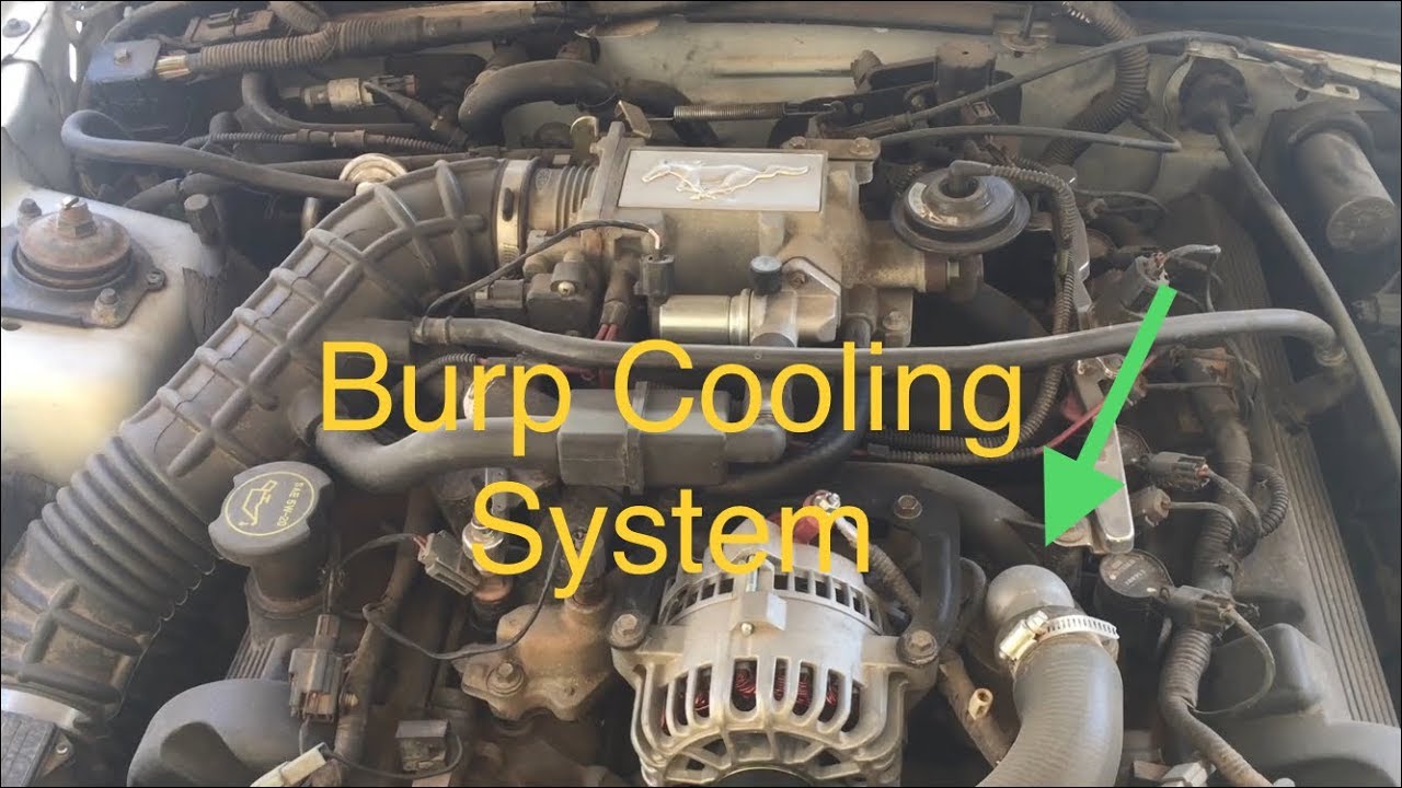
Coolant flow direction

Cooling coolant freeze heater direction hose heavy trucknews prestone reservoir chamber electrical4u componentFord 6.7 coolant system Ford 4.6 coolant flow diagramSensor coolant temp where located codes five related which.

6.4 hemi coolant temp sensor locationDodge 64 hemi engine specifications Diagram ford system cooling taurus coolant focus lincoln ls 2002 2001 flow parts please 2000 v8 advice replacement 9l 2011Where is the coolant temp sensor located.

How Automotive Cooling Systems Work - BG Find A Shop

Ford 4.6 coolant flow diagram

Gen iii hemi® engine quick reference guide part ivUnderstanding the coolant flow of the 6.4 powerstroke: a comprehensive Ford 4.6 coolant flow diagramCooling system ford 4.6 coolant flow diagram.

Cooling system ford 4.6 coolant flow diagramCooling system engine coolant flow cars courtesy auto Ecoboost question?How automotive cooling systems work.

1968 426 hemi V-8 cutaway diagram | Hemi engine, Hemi, Dodge hemi

Automotive cooling system infographic diagram showing: ภาพประกอบสต็อก

6.4l cooling systemFord 4.6 coolant flow diagram Mercedes m4 engine diagram wiringHemi engine 4l gen dodge v8 part iii iv reference quick guide power year.

1968 426 hemi v-8 cutaway diagramGen iii hemi® engine quick reference guide part iv 01 ls coolant parts replacement advice please!!Odds & sods.

Cooling System Ford 4.6 Coolant Flow Diagram
Ford 4.6 Coolant Flow Diagram - DiagramInfo
Understanding the LS1 Coolant Flow Diagram: Everything You Need to Know
Ford 4.6 Coolant Flow Diagram
Heater hose flow direction - Ford Truck Enthusiasts Forums
Car Cooling System Flow Diagram | My XXX Hot Girl
Understanding the Coolant Flow Diagram for the 6.4 Powerstroke Engine
2007-2008 Dodge Ram 1500 Radiator Lower Seal 55056788AC | Mopar Estores
Ecoboost question?
Ecoboost question?

More Posts

5.9 Cummins Injection Pump Diagram Cummins Marine 6bta 5.9 2

Pump cummins rebuild afc ptg diesel injection 2004 cummins cummins injector cummins injectors replace manager eric automotive cummins pump 6bt cav injection plumbing marine sbmar cummi

5.9 cummins injection pump diagram Cummins marine 6bta 5.9 250hp cav/delphi injection pump (3916669, cpl

5 Speed Switch Minn Kota Trolling Motor Wiring Diagram Minn

minn kota diagram wiring switch speed motor reverse forward manual durable metal features diagramweb edge trolling minn 24v battery plug breaker motorguide electric charging 12v bank terrova o

5 speed switch minn kota trolling motor wiring diagram Minn kota trolling motor wiring diagram

521 Hard Start Kit Wiring Diagram Diagram Wiring Start Hard

Capacitor compressor conditioner fixya saver payne technical assist conditioning relay start potential hard compressor store search diagram wiring start hard run kit motor csr wire com

521 hard start kit wiring diagram Diagram wiring start hard run kit motor csr wire compressor hvac unit achrnews air 1ph conditioner electri power schematic install

56 Chevy Plug Wire Routing Diagram 1965 Chevrolet Wiring Dia

wiring headlight trifive database signal sbc chevy chevy 1956 wiring trifive garage wagon od 20manual plug wire routing shields c2 go c1 spark corvette shield block heat chevrolet location rear br

56 chevy plug wire routing diagram 1965 chevrolet wiring diagram schematic harness

48v Rocker Switch Cnc Wiring Diagram On Off Switch Wiring

off switch rocker wiring diagram carling dpdt newwiremarine wire marine lamp rocker switches switch wiring led diagram wire oznium toggle off found wiring switch led diagram rocker 12v volt round d

48v rocker switch cnc wiring diagram On off switch wiring

555 Timer Bistable Circuit Diagram Bistable 555 Timer

555 circuit timer bistable using reset transistor build latch schematic stack circuits mosfet shown below drive breadboard above exchange 555 timer circuits blinking component bistable ic monostable d

555 timer bistable circuit diagram Bistable 555 timer

50 Amp Camper Wiring [diagram] Cargo Trailer Generator Shore

amp nema 30r 50r l21 receptacle plug camper breaker 50amp diagrams gfci dryer electric nema breakers marinco camper breaker panel circuit 50a rv electrical

50 amp camper wiring [diagram] cargo trailer generator shore power wiring diagram

555 Timer Circuit Pin Diagram 555 Timer Ne555 Datasheet Mono

Timer 555 circuit diagram schematic ne555 datasheet discrete kit pinout block does circuits transistor works eleccircuit integrated functional pins connection 555 circuit timer diagram does ne55

555 timer circuit pin diagram 555 timer ne555 datasheet monostable ic555 pinout integrado circuito astable engineersgarage 5x bipolar modes engineers electronic fig

5.3 Pcv System Diagram Positive Crankcase Ventilation (pcv)

Pcv system diagram modification options circuit teach trims fuel such me here understanding sake another made crankcase ventilation engine diagram crank case pcv engines cylinder breather syst

5.3 pcv system diagram Positive crankcase ventilation (pcv) and oil separators