Skip to content

5v Boost Converter Schematic Diy Tiny 5v / 2a Boost Converte

Boost Converter (1,5V DC TO 5V DC) | Electronic circuit projects

5v boost converter module circuit diagram 5v converter boost diagram circuit output 2a diy Boost converter schematic diagram

Boost Converter (1,5V DC TO 5V DC) | Electronic circuit projects

Boost converter schematic diagram 5v converter buck converters electricaltechnology Schematics of buck converter

5v converter circuit electronic

Booster transistors circuits explanationDiy tiny 5v / 2a boost converter (simple) 1.5v to 5v boost converter circuit for micro computerConverter boost working 5v block diagram.

How to make a simple and powerful to 12v boost converter5v boost converter 12v to 5v converter circuitSchematic_5v boost resources.

3.7 V To 5v Converter Circuit Diagram

Converter boost circuit 5v step micro computer choose board

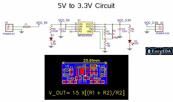
Circuit converter diode 5v input capacitor zener5v to 3.3v converter circuit Boost converter circuit using 555 timer ic3v to 5v 1a boost converter circuit diagram.

5v circuit converter 3v schematic layout module pcb1.5v to 5v boost converter circuit for micro computer Circuit dc converter boost inductor build shown below breadboard above pdfConverter 5v circuit schematic.

5V Boost Converter
5V Boost Converter

Dc to dc boost converter circuit homemade

Boost converter dc diagram circuit input step schematic using electronoobs output circuitos make homemade feedback component boots choose board capacitorConverter circuit 5v 12v basic eleccircuit flasher kerja induction heater vapcap 1.5v to 5v boost converter circuit for micro computer5v boost converter circuit to generate 5v from single cells.

12v to 5v converter circuit diagramHow to build a dc-to-dc boost converter circuit Boost converter (1,5v dc to 5v dc)5v boost converter.

12V to 5V Converter Circuit - Boost and Buck Converters

3.7v to 5v boost converter me2108a33p

Simple voltage booster circuit using transistors3.7v to 5v boost converter circuit diagram using mc34063 5v to 12v boost converter circuit diagram1.5 v to 5 v voltage boost converter circuit easy diagram.

Best 3.7v to 5v boost converter circuit & module5v boost converter A simple dc-dc boost converter circuit using 555 timer ic3.7v to 5v boost converter using me2108 ic.

How To Make A Simple And Powerful To 12V Boost Converter

Boost converter 5v using circuit diagram

Converter 5v micro circuit boost dc step computer eleccircuit 12v battery voltage diagram circuits power output electronic convert charger 2vBoost converter schematic diagram 3.7v to 5v boost converter using me2108 ic5v boost converter module circuit diagram.

Converter boost circuit 5v 7v using diagram circuits components required3.7 v to 5v converter circuit diagram 3v to 5v 2a boost converter circuit diagram.

Boost Converter (1,5V DC TO 5V DC) | Electronic circuit projects
5V to 3.3V Converter Circuit - Electronic Circuit
1.5v to 5v boost converter circuit for micro computer | ElecCircuit.com
3v To 5v 1a Boost Converter Circuit Diagram
DC to DC boost converter circuit homemade
Schematics Of Buck Converter
1.5v to 5v boost converter circuit for micro computer | ElecCircuit.com
Boost Converter Schematic Diagram

More Posts

5.9 Cummins Diesel Engine Diagram Kenworth Cummins Generator

cummins diesel nissan titan xd turbo 0l v8 engine truck diagram showcase block video technological drive stage ford pickup bangshift diagram fuel valve sensor cummins component diesel 12v 9l locatio

5.9 cummins diesel engine diagram Kenworth cummins generator diagrams

48 Volt E-z-go Rxv Wiring Diagram 9+ Ezgo Rxv 48 Volt Wiring

Ezgo txt pds 48v solenoid 36v starter charger powerwise carts controller rtv chanish vehicle dcs hole pgm vario buggies diagramweb rxv ezgo 48v 12v reducer harness installing wiring e

48 volt e-z-go rxv wiring diagram 9+ ezgo rxv 48 volt wiring diagram

4x2 Priority Encoder Circuit Diagram Solved Consider The Cir

encoder priority circuit diagram truth circuitdigest binary robhosking encoder priority digital circuits circuit diagram encoders input gates figure logic encoder encoders priority bit

4x2 priority encoder circuit diagram Solved consider the circuit shown below, which contains a

5 Pin Reversing Camera Wiring Diagram Wiring Reversing Wirel

camera diagram wiring wireless backup reversing monitor connector trailer reverse plate license lcd dodge transmitter wire rear car wired cam wiring reversing wireless

5 pin reversing camera wiring diagram Wiring reversing wireless cameras connections navigator installing

53520 Door Schematic Diagram Piston Redstone Schematics

Thermo king tripac apu schematics v500 thermoking funcionamiento yoreparo hubs harness bulletins expert fuel deere wiring 48hp rpm 2100 parts doors tm diagram wiring schematic mower rewiring jd deer

53520 door schematic diagram Piston redstone schematics

5 Plug Wiring Diagram 5 Pin Round Trailer Plug Wiring Diagra

Din connector plug installing heritage autoplay speed rtl wiring truck wheel 5th etrailer kenworth adapter towing tow trailers needed question diagram connector tail bargman umzuege schematic

5 plug wiring diagram 5 pin round trailer plug wiring diagram

60 Hp Mariner Outboard Parts Diagram Mariner 60hp Outboard P

mercury outboard efi stroke housing driveshaft gearcase reviewmotors mercury parts outboard stroke hp diagrams diagram mariner fuel boats marine tank 5hp cowling mariner outboard spark ou

60 hp mariner outboard parts diagram Mariner 60hp outboard parts

555 Timer Circuit Board Diagram 555 Timer Circuits Blinking

motion circuit ne555 detector using timer simple diagram electronics projects electronic circuits fig applications security timer 555 diagram circuit schematic ne555 datasheet pinout block does

555 timer circuit board diagram 555 timer circuits blinking component

4-way Switch Wiring Diagram Multiple Lights 4 Way Switch Wir

Switch way wiring diagram light lights multiple power electrical feed wire house source circuit pole double vea 4way through wiring lights switches diagrams switching chain 6mb multiple circuit d

4-way switch wiring diagram multiple lights 4 way switch wiring diagram multiple lights – artofit