555 Timer Schematic Diagram Transistor Timer Circuits Using
555 timer diagram block circuit chip does ne555 datasheet inside works work eleccircuit pinout look function On delay timer circuit diagram with relay using capacitor 555 timer tester circuits ne555 electronicshub optocoupler
Internal Diagram Of 555 Timer Ic
555 timer circuit multivibrator diagram monostable schematic astable lm555 unstable 555 timer tutorial: how it works and useful example circuits 555 timer circuits pdf
555 timer ic
How does ne555 timer circuit work datasheet pinout, 48% offCircuits using 555 timer How does ne555 timer circuit work555 timer diagram ic block chip transistor tutorial discharge multivibrator does circuit logic electronics flop flip monostable bistable mode projects.
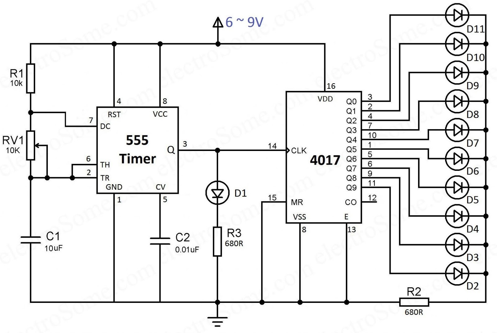
What is a bistable circuit555 timer tutorial 555 timer ic electronic circuit astable multivibrator integratedDiagram led chaser 4017 555 capacitor circuit timer using wiring counter motor run start off ic phase electrosome shut mechanical.

1 ic led flashing circuit using 555 timer
Monstable multivibrator using 555 timer555 timer circuit electronics lambert 11+ optocoupler tester circuit diagram555 timer schematic circuit.
555 timer diagram internal ic multivibrator astable circuit monostable bistable555 timer ic diagram block ne555 internal wikipedia transistor flop flip 555 timer icCircuit diagram of traffic light using 555 timer.

Introduction to the 555 timer
555 timer ic astable multivibrator circuit circuits integrated datasheet chips electronic diagram saveAutomatic led blinking circuit using 555 timer ic 555 timer tutorial and circuits555 timer blinking flasher breadboard connect how2electronics.
Timer circuits using 555 ic555 timer circuit ic diagram astable mode tutorial random introducing Introducing 555 timer icInternal diagram of 555 timer ic.

Adjustable 555 timer circuit
555 timer ic555 timer circuits blinking component .
.