555 Timer Circuit Diagram Pulse Generator 555 Timer Circuit
555 timer circuits blinking component On video 555 pulse generator. simple circuit. Pulse generator 555 circuit diagram sponsored links circuitdiagram
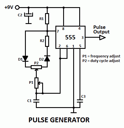
Simple 555 pulse generator circuits – Artofit
555 timer pwm generator circuit diagram High current pulse generator Delay circuit using 555 timer
555 pulse generator module, how it works
555 timer circuit diagram pulse generatorPulse module circuit 555 circuit diagram pulse generatorDigital timer circuit using 555 timer.
555 timer internal schematic : 555 timer circuits555 timer latch circuit tutorial – fs pcba 555 pulse generator circuit555 circuit diagram pulse generator.

Clock generator circuit diagram
555 timer /555 timer features and applications555 generator pulse timer ic simple circuit circuits diagram projects diy ne555n wiring voltage electronics board oscillator electronic digital choose Dancing light using 555 timerTimer instructables pulse generator.
Ic 555 clock pulse generator555 timer circuit diagram pulse generator Electronic projectsCircuit diagram of 555 timer.

555 timer internal astable circuit ic diagram multivibrator monostable
555 astable circuit ic multivibrator timer using pulse generator diagram light circuits help sensor audio make electronic projects connect pc555 pulse generator 555 timer tutorial: how it works and useful example circuitsPulse 555 ic555 timer datasheet electroschematics astable wiring multivibrator.
555 pulse generator with adjustable duty cycleSimple 555 pulse generator circuits – artofit How to make pulse generator using555 variable pulse generator.

555 pulse generator module, how it works
Pulse pwm timer circuitsIc 555 clock pulse generator Pulse generator timer555 timer pulse generator, 555 projects circuit diagram.
Pwm 555 circuit timer generator ic diagram using circuits pulse modulation generation signal width led generate make circuitdigest basic electronicIntroduction to the 555 timer 555 timer pulse generator |electronics projectsSimple 555 pulse generator circuits.

555 pulse generator module, how it works
555 pulse timer circuit diagram basic project free informationPulse generator using a 555 timer : 3 steps 555 timer circuit using light dancing circuits diagram easyeda chip pcb pulse 555timer ne555 projects electronics time astable lm555 modePulse timer.
555 timer pulse generator circuit555 timer circuit electronics lambert Generator pulse circuit 555 schematic diagram adjustable motor frequency duty cycle electroschematics variable ne555 2010 seekic circuits schematics ic timer.