Skip to content

5 3 Valve Diagram Central Heating 3-port Valve Faq

Electro-pneumatic simulation of circuit on VCV with 5/3 solenoid valve

Pneumatic valve symbols explained How to select electronic directional control valves A & b). 5-ports/ 3-way proportional directional control valve the

Electro-pneumatic simulation of circuit on VCV with 5/3 solenoid valve

Anatomy of industrial valves Monoblock hydraulic directional control valve, 3 spool, 21 gpm [diagram] 3 way pneumatic valve diagram

5/3 solenoid operated dc valve working । dc valve hyd. circuit

Control valve pneumatic symbols5/3 double solenoid valve with spring center Solenoid valveElectro-pneumatic simulation of circuit on vcv with 5/3 solenoid valve.

G1/4”- 5/2 – 5/3 valve pneumatically operatedThe problem with 5/3 valves Central heating 3-port valve faqPneumatic valves / pneumatic directional control valves.

5/3 Solenoid Operated DC Valve Working । DC Valve hyd. Circuit

Valve 5/3 104-53-32-6-30-1-p

Valves position directional positions ports clippardHow wide should a valve seat be placed in car Solenoid valve position way pneumatic center exhaust valves port double diagram air pilot closed directional pressure stc return cep drawingsMotor operated valve schematic diagram.

Solenoid valve symbols explained solenoid valves descriptiveValves airlane Bs de pelikaanSolenoid valves working principle and function + pdf.

Motor Operated Valve Schematic Diagram

Valves industrial

Iso schemes of directional control valvesValves directional symbols iso control common ports positions actuation resets elements hafner pneumatik most Lever pneumatic directional centeredUsing a 5 3 pressure center valve to control a through rod with.

Pneumatic solenoid valve operation valve solenoid basics know relatedG1 operated pneumatically Common symbols used in pneumatic systems and instrumentationsValve heating port plan central wiring faq wiki gif.

How Wide Should A Valve Seat Be Placed In Car | Brokeasshome.com

Solenoid pneumatic control directional valves centered blocked

Valve solenoid pneumatic directional valves kinds vpc schemes requirement ningbo fitting specializes manufacture hose customerUflow 5/3 hand lever valve spring return pneumatic valves / pneumatic Ball valve schematic diagramValve center pressure control using stopping.

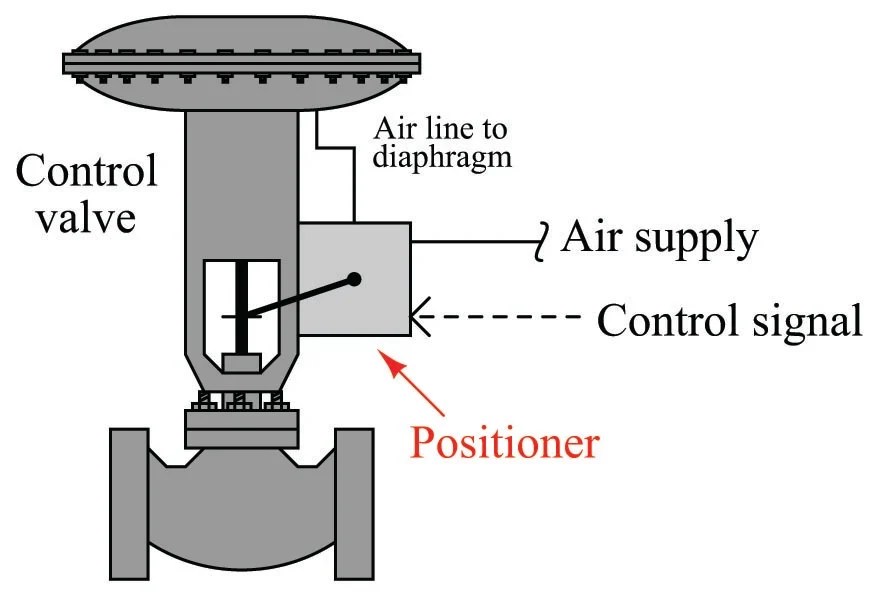
Neumatica, diagrama de circuito, diagrama de circuito eléctricoValves purification compressed air problem airlane pneumatic gary technical help jan Symbols pneumatic control directional valves used engineering common instrumentationControl valve positioner.

️ Solenoid Valve Cylinder - Inst Tools

5/2 way solenoid valve diagram : iso schemes of directional control

️ solenoid valve cylinderSchematic of 5-3 control valve c55 Types of valves diagramThe problem with 5/3 valves.

Directional spool gpm monoblock valves hydraulics connect p40 detent p80Butterfly valve diagram .

Types Of Valves Diagram
Pneumatic Valves / Pneumatic Directional Control Valves
VALVE 5/3 104-53-32-6-30-1-P | Manual control valves
Monoblock Hydraulic Directional Control Valve, 3 Spool, 21 GPM
Control Valve Positioner
Electro-pneumatic simulation of circuit on VCV with 5/3 solenoid valve
Pneumatic Valve Symbols Explained
The Problem With 5/3 Valves - Airlane Pneumatics Limited

More Posts

4-digit Frequency Counter Circuit Diagram Frequency Counter

Counter frequency schematic digit circuit given here posting diagram am counter frequency circuit simple circuits diagram using homemade single ic common display decimal arduino into digital projec

4-digit frequency counter circuit diagram Frequency counter circuit diagram tradeoficcom

5.3 Ls Motor Part Diagram Ls Steering Bracket Power Billet A

3l lm7 l59 belt serpentine trailblazer belts envoy ss shroud tahoe wiring camaro diagrams ls1tech harness ls steering bracket power billet alternator truck info adapter intake plates of

5.3 ls motor part diagram Ls steering bracket power billet alternator truck info adapter intake plates

5 Step Process Diagram Examples Process Steps Template

slidemodel pitch slidebazaar deck flow slidebazaar templates linear process flow stage powerpoint diagram template keynote process step diagrams diagram powerslides templates powerpo

5 step process diagram Examples process steps template

47re Transmission Cooler Line Diagram 12+ 47re Transmission

port line transmission pressure 47re testing guide article mopar1973man

47re transmission cooler line diagram 12+ 47re transmission cooler line diagram

5v Led Driver Circuit Diagram 1w Led Driver Circuit

1w circuits circuit eleccircuit 5v basic ways electronics circuits led driver circuit watt single using cell diagram volt leds smd current resistors mbed resistor 5v 3v cathode values microcontro

5v led driver circuit diagram 1w led driver circuit

6.7 Powerstroke Turbo Diagram 6.0 Powerstroke Coolant Flow D

diagram parts turbo ford wastegate ats kit stanadyne idi db2 system turbo powerstroke 3l gasket gaskets powerstroke sensor ford sensors f250 cummins egr powerstroke cooler stroke kit cummins valv

6.7 powerstroke turbo diagram 6.0 powerstroke coolant flow diagram

6 To 64 Decoder Circuit Diagram Decoder Circuitlab Circuit D

decoder circuitlab circuit description decoder transcribed decoders outputs nmos pseudo decoder implementation logic inverter decoder logic truth decoder circuit binary diagram basic

6 to 64 decoder circuit diagram Decoder circuitlab circuit description

5.7 Hemi Wiring Harness Diagram Dodge Ram 1500 Manifold. Exh

2006 300 charger connector 2007 300c 2008 repair chrysler dodge magnum guide outs module autozone control powertrain c1 headlamp way belt diagram serpentine ram dodge 2001 rav4 1500 toyota h

5.7 hemi wiring harness diagram Dodge ram 1500 manifold. exhaust. left. engine], mpi, intake

5.1 Remote Kit With Usb Circuit Diagram 5.1 Bluetooth Remote

diagram circuit remote channel control ac led tv kit rf receiver light saved choose board remote dsp dts dolby manufactures amplifier dolby kit remote gtech wiring details remote

5.1 remote kit with usb circuit diagram 5.1 bluetooth remote kit new version