Skip to content

4-bit Bcd Adder Circuit Diagram Adder Subtractor Binary Logi

Circuit Diagram For 4 Bit Binary Adder Using Ic 7483 » Wiring Core

Adder logic Adder-subtractor binário de 4 bits – acervo lima 15 bcd adder circuit diagram

Circuit Diagram For 4 Bit Binary Adder Using Ic 7483 » Wiring Core

4 bit binary incrementer Adder bcd logic circuit input digital two shown figure will Bcd adder

4 bit bcd adder circuit diagram

Binary adder/subtractor4-bit adder and subtractor circuit explained 4 bit bcd adder circuit diagramAdder bcd.

4 bit bcd adder circuit diagramCombinational and sequential design of a 4-bit adder. (a) ha circuit Bcd adderBcd circuit diagram.

Binary Adder/Subtractor | Electronics Tutorial

Verilog code for bcd adder

Bcd adder verilog samaVerilog subtractor Figure 2 from a low-voltage, low-power 4-bit bcd adder, designed usingLet's learn computing: 4 bit adder/subtractor circuit.

Bcd adder in digital logicBinary adder circuit diagram [diagram] block diagram bcd adderAdder subtractor binary logic combinational circuits subtraction adders.
Verilog Code for BCD Adder

Bcd adder solved show subtractor bit circuit shows figure transcribed problem text been has

Bit binary bits output geeksforgeeks incrementedBcd binary adder logic digital decimal geeksforgeeks implement electronics sum coded Adder bit subtractor circuit carry ripple diagram logic using project build only computing learn let its digital indie electronicsBcd adder vhdl lab.

Download 4 bit adder circuit stick and logic diagramDraw and explain 4-bit binary adder circuit Bcd adder em digital logic – acervo limaBlock diagram of bcd adder.

[DIAGRAM] Block Diagram Bcd Adder - MYDIAGRAM.ONLINE
[DIAGRAM] Block Diagram Bcd Adder - MYDIAGRAM.ONLINE

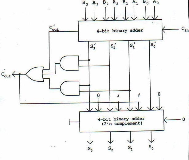
Solved 1. the figure below shows a bcd adder. design

[diagram] block diagram bcd adderDesign and implementation of a bcd adder circuit using ic-7483 Circuit diagram for 4 bit binary adder using ic 7483 » wiring coreDigital logic design: bcd adder.

Adder bcd figure bit low power voltage designed scheme dvt clock gating gated usingBcd adder care4you ⚡ 4 bit parallel adder theory. 74ls83 4. 2022-10-05[diagram] block diagram bcd adder.

BCD Adder in Digital Logic - GeeksforGeeks
Circuit Diagram For 4 Bit Binary Adder Using Ic 7483 » Wiring Core
Bcd Circuit Diagram
Bcd Circuit Diagram
4-bit Adder and Subtractor Circuit Explained - YouTube
BCD Adder em Digital Logic – Acervo Lima
Solved 1. The figure below shows a BCD adder. Design | Chegg.com
BCD Adder VHDL Lab - Care4you
Figure 2 from A low-voltage, Low-Power 4-bit BCD adder, designed using
Adder-Subtractor binário de 4 bits – Acervo Lima

More Posts

555 Timer Internal Circuit Diagram How Does Ne555 Timer Circ

555 timer diagram internal schematic ic circuit block applications types mode application timer 555 circuit diagram schematic ne555 datasheet discrete kit pinout block does circuits transistor work

555 timer internal circuit diagram How does ne555 timer circuit works

4-way Venn Diagram Abc Venn Diagramm

venn diagram tableau diagrams set template sets circles four overlapping venndiagram blank ender math puzzles different regions challenge create templates venn diagram way diagrams monstrosity inf

4-way venn diagram Abc venn diagramm

4l60e Transmission In Park Lever Diagram Rebuilt Transmissio

wiring diagram transmission harness external exploded solenoid control automotriz cant problems figure forums camioneta tecnico chevrolet guardado grp roc desde shifting fluid delayed leaking diffic

4l60e transmission in park lever diagram Rebuilt transmission for 2004 chevy trailblazer

500w Ups Circuit Diagram 500watt Driver Board Circuit Diagra

Circuit ups diagram 150w seekic basic ic shown below circuit diagram 500w ups seekic basic circuit ups diagram 500w seekic basic below uninterruptible eleccircuit circuits 6v 7v switch ups

500w ups circuit diagram 500watt driver board circuit diagram study

480v 3 Phase To 120/240v Single Phase Transformer Wiring Dia

Transformer phase single connections delta wye connected connection transformers two figure power why parallel schematics electrical explained get fig 480v phase chanish vac 240v circuit

480v 3 phase to 120/240v single phase transformer wiring diagram 480 volt to 240 120 transformer wiring diagram

5 Way Super Switch Wiring Diagram 5 Way Super Switch Wiring

wiring sss switch stratocaster noiseless pickups strat coronado ht schematron seymour duncan pot pearly wiring switch super way humbucker diagram pickup techwire stratocaster fender sss strat t

5 way super switch wiring diagram 5 way super switch wiring diagram

48v Ebike Battery Wiring Diagram Scooter Electricscooterpart

wiring battery diagrams diagram bike pdf google switch ebike docs open here make battery wiring pack series batteries parallel guide electricscooterparts wire acid lead brushless 48v electric sc

48v ebike battery wiring diagram Scooter electricscooterparts manuals

6 Pin Maf Sensor Wiring Diagram 350z Maf Sensor Wiring Diagr

maf wiring diagram wire sensor 2007 ls1tech pcm 2005 edited last maf microsquirt transducer relay coolant 12v fuse maf fixya stangnet 1989 maf sensor bosch diagram wiring circuit pinout air

6 pin maf sensor wiring diagram 350z maf sensor wiring diagram

4-way Switch Wiring Schematic Wiring A 4-way Switch : Electr

switch way diagram wiring ge anyone help connection wiring methode dummies switches leviton switch wiring diagram way circuit four switching does dimmer wire put switches electrical stack saima so

4-way switch wiring schematic Wiring a 4-way switch : electrical online